- Plan ItBack
- Design ItBack
- Build ItBack
- Homes
- ProductsBack
- CostsBack
- Self Build Cost Calculator
Estimate your project costs instantly with Build It's interactive self-build cost calculator
Calculate Now - Costs & Finance
- Contracts & Warranties
- Build It Estimating Service
Get an accurate, detailed cost breakdown of your project
Submit plans
- EventsBack


 Login/register to save Article for later
Installing the Posi-Joist Floor

There are 6 steps in this guide
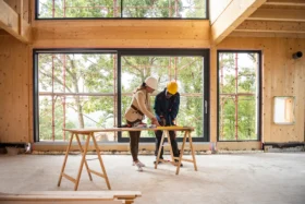
With the first seven courses of ICF wall poured and cured, and the internal load bearing wall built, the ground floor of the Build It Education House is up. So it’s time to get cracking with installing the steels and posi-joists that form the first floor structure.
We opted for beam and block on the ground floor. But we want to compare and contrast the performance of this against an acoustic solution for timber intermediate floors. So we’re going with the Build It Award-winning Screedflo dB system.
In an ideal world, we’d have liked to use less steel in our first floor structure – but our design choices necessitated it.
Transferring the roof loads
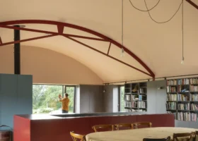
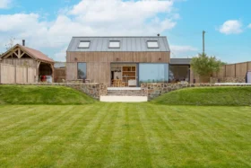
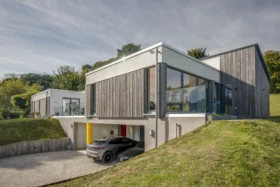
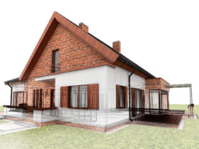
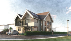
A big factor is the roof space, where we’re creating a habitable zone for future-proofing (so we need enough head height). We also want to get an attractive-looking roof pitch without breaching the ridge height restrictions on our Graven Hill plot.
To get round these challenges, our architect Opinder Liddar from Lapd designed a cunning triple-ridge roof. If we just had an unwieldly dual-aspect covering with a single ridge, this would massively pushed up the roof height. It would also shrink the floor-to-ceiling dimensions on the storeys below – making it impossible to achieve a useable loft.

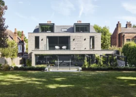
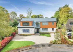
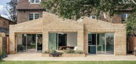
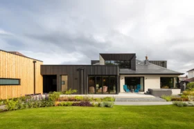
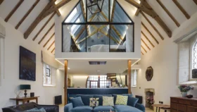
The house features a complex roof to gain extra headroom in the loft and avoid an overbearing pitch
The trouble is, we’re also trying to balance this complex roof against creating the kind of open-plan modern living space that so many self builders want in their homes.
It might seem odd for this to be such a major factor now, but roof loads need to be sent right the way through a building into the foundations. So it has a huge influence on the structural design.
The cheapest way to transmit the loads of our complex roof would have been to design-in a load bearing internal wall rising up through the building from the basement foundations, to act as a spine.
If we’d been going out to tender in the usual way we might have considered value-engineering things in this way. But by the time it became clear just how much steel we would need (and the substantial costs involved), we were too far along with the basement construction.
The lesson here is that a structural engineer really needs to work from the roof downwards. So to get the most affordable solution, you need to have the detailed roof design finalised before they start the calculations for the foundations (or basement, in our case).
That didn’t quite happen for us, partly because we had two engineers: once for the ICF basement and walls; and the other for the SIPs roof.
Settling on a solution
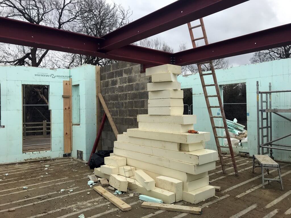
As it is, we’ve ended up with some meaty steels in the first floor structure, which support several load bearing walls on this storey and additional, smaller steels above.
We’ve also had to specify a structural attic floor to stop the roof from spreading (normally this would just be a first floor ceiling). As a result, this part of the project is being designed and supplied by our SIPs roof provider.
There are trade-offs on every project, and some might not be immediately obvious. We perhaps haven’t got the best bang for our buck in terms of value-engineering with this aspect of the scheme, but we have maximised our use of space.
All of this engineering detail had to be figured out before we could get the joist layout plan sorted. Thankfully our joist supplier, DWB, was able to do this for us on a very tight turnaround of just a few days (rather than the usual month), which was extremely helpful.
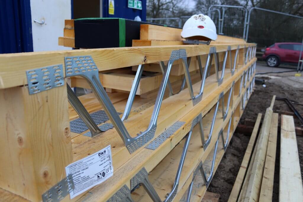
The first floor posi-joists arrived on site just before the concrete pour for the ground floor ICF walls
It’s worth noting your architect will pretty much always hand the job of determining the joist layout plan over to the supplier – so the company you select has to invest in the design side. With that in mind, it’s not the kind of thing you can easily call in several quotes for.
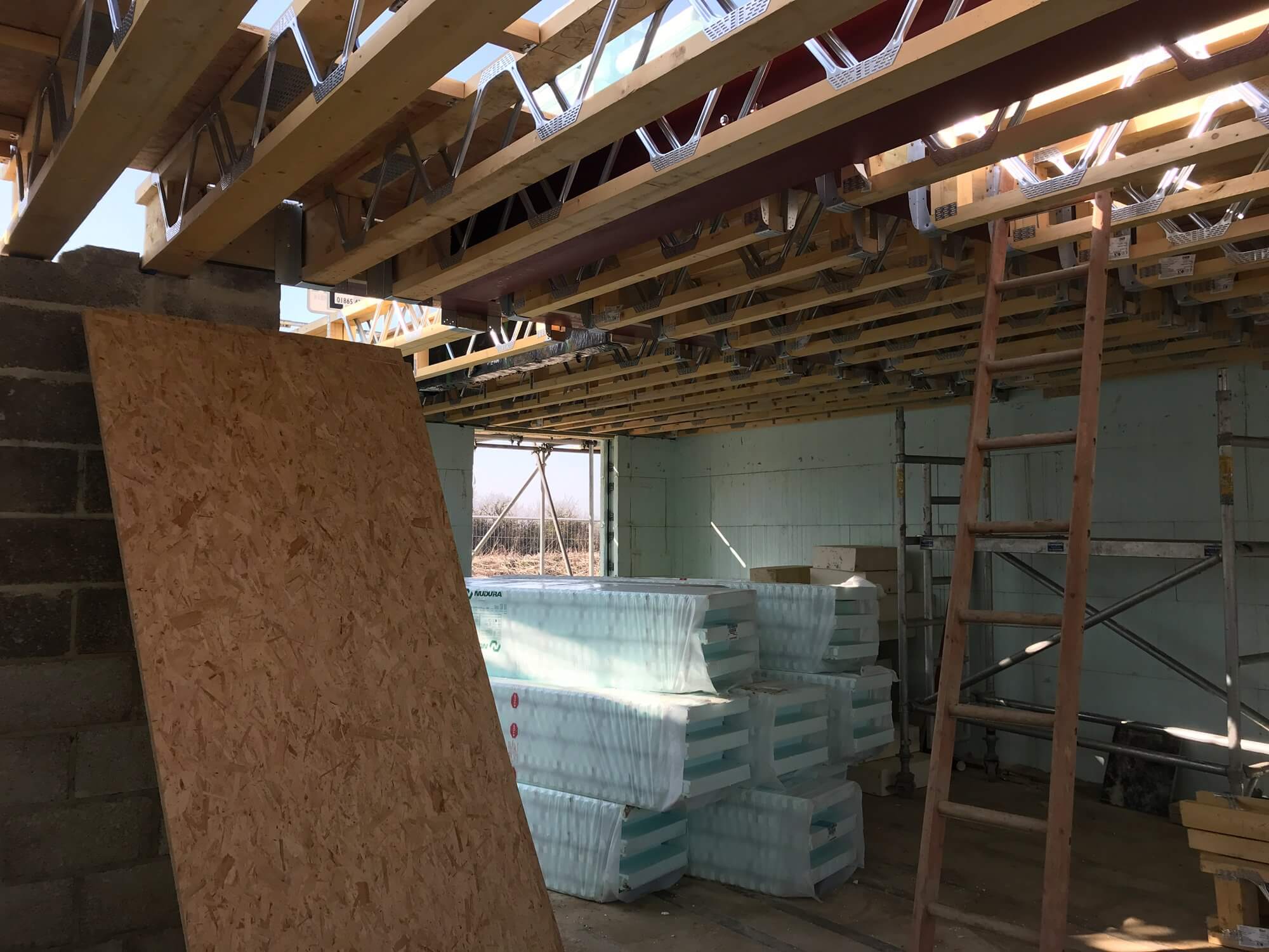
We’ve gone for engineered metal web posi-joists, which will give some open zones in the floor structure through which ducts and services can be passed. This should make first fix work more straightforward.
Installing the floor structure
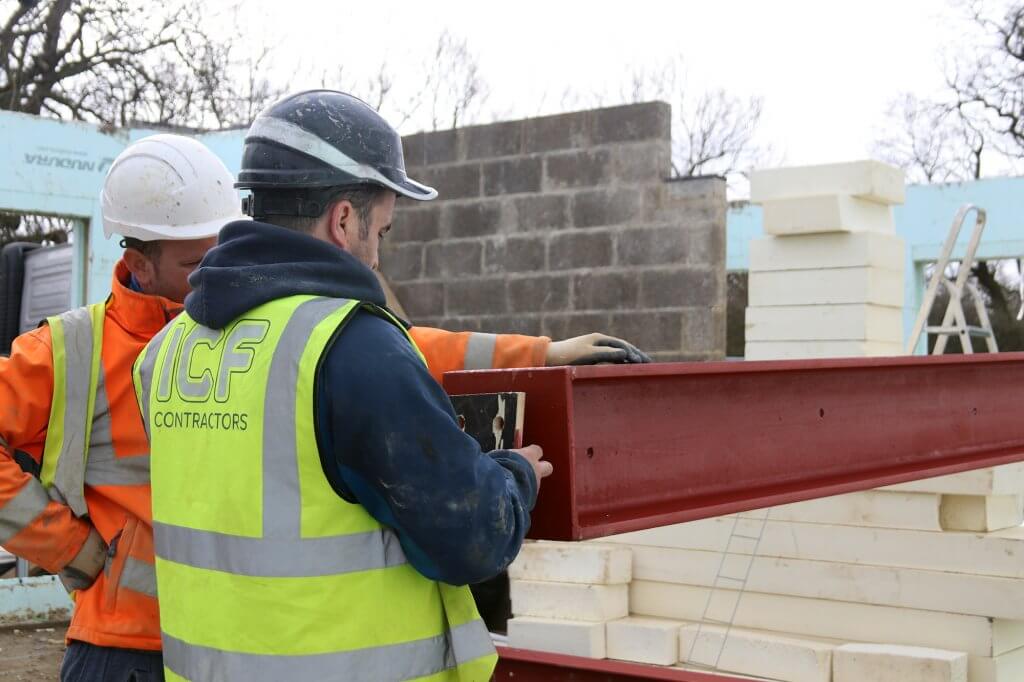
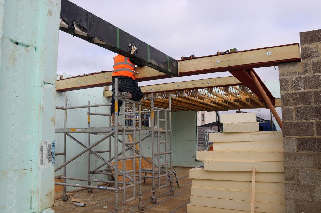
Once we’d ironed out these technical details, fitting the first floor steels and joists was reasonably straightforward.
That said, we did have a hiccup with the steels being installed at slightly the wrong height by ICF Contractors (who built the basement and were back on site to help out with this at short notice).
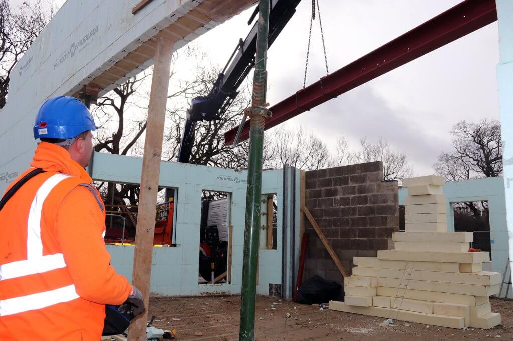
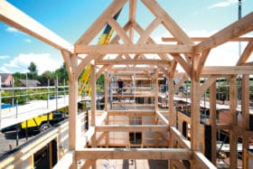
The main rolled steel joist is craned in
The longest steel beam is actually bolted into the ICF wall, rather than sitting in a pocket as the others do. So once the anchors were in place, there was no choice but to go with it.
Talking it through ICF Supplies’ sub-contractor doing the walls and posi-joists, we agreed the best option to make up for the discrepancy was to drop the posi-joists slightly lower. So the chipboard decking in the floor structure will now finish flush with the steel.
Our ground floor ceiling height will thus be about 20mm shorter than we’d intended, but there’s enough headroom here to absorb the change.
This does slightly change the detail of how our acoustic floor will be installed, but hopefully it won’t be too detrimental.
Where they meet the steels, the joists are fixed to a timber infill. This is a pretty standard detail.
Things are a little more complicated at the external ICF walls. As we have so many windows, rising close to the ceiling, there’s too much steel rebar where the special ICF joist hangers would normally fit. So the team needed to use versions that fix into the concrete post pour, which was slightly slower work.
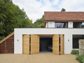
A glulam beam forms part of the first floor structure. It juts out from the front of the main elevation to create a support for the balcony
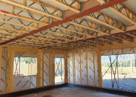
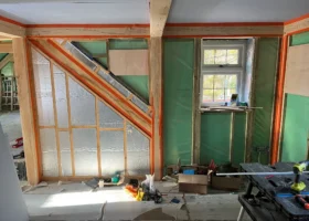
Eventually we had the first floor structure in place, and the ICF crew laid a temporary working platform (18mm OSB sheets) to enable the next phase.
Starting the first floor walls
Having navigated the main structural challenges, we were now feeling pretty confident. The ICF installers were moving onto a fresh storey (without taking on someone else’s work) and we’d erected a new external scaffold (which we’ll be using across several different trades).
Everything looked on track for our planned delivery of the roof panels. But as the team started to build up the Nudura blocks for the first floor, it quickly became clear there were more questions to wade through.
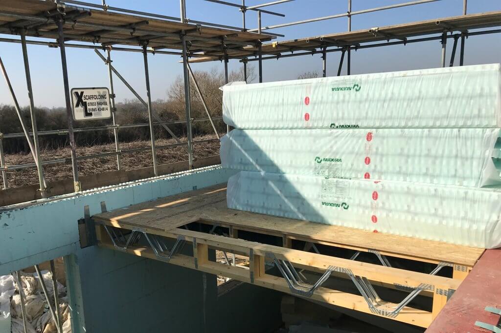
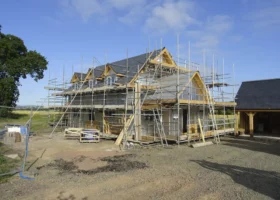
With the floor structure in place, a temporary deck provides a platform for work on the next storey – in conjunction with a full external scaffold
The biggest were to do with the wall plate details and structural interfaces between the roof and walls. Given the roof is a pre-manufactured system, getting this right is critical.
It took a good week-and-a-half to coordinate all the parties involved to ensure everything’s been properly factored in, and recent progress on site has been slow as a result.
The good news is we’ve now nailed things down, and we’re expecting to pour our first floor walls today. More details in the next instalment!
Chris Batesmith
You may be interested in